Power Bank Inside a USB Cable 10 Steps with Pictures Circuit Diagram Here is simple circuit to keep your USB Power Bank active "awake" so it stops automatically shutting off. Click the SHOW MORE tab below for links. *Building The power is stored in a power ban by charging and it can be used when you need, In any power bank, A battery or combination of some small special batteries (cells) used to produce the power source to provide for mobile or other electronic gadgets battery charging. The USB port is used to input for charging and also for output. It has a circuit

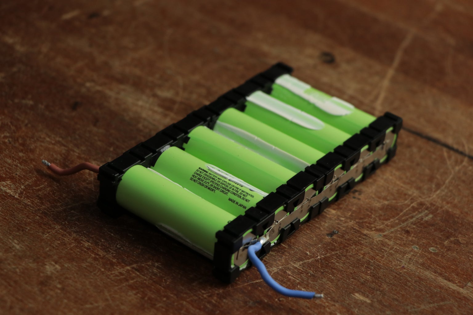
This DIY USB Power Bank packs 18650 battery cells and a power management board into a 3D printed case. The four cells provide 16,000 mAh, which should give you a few charges.
Power Bank Stay Awake! Here's A Circuit To Do That: Circuit Diagram
The following components are required to make Power Bank Circuit. First place and solder the female USB port and 12DC input pin on the Vero board. Now, connect a resistance of 1K in a way that one end is connected to a 12V pin and one end to the positive pin of the LED. Connect the negative of an LED to a 12V negative pin.

Charging the Power Bank Circuit: Red color LED indicates the battery charging in this power bank circuit, Blue color LED indicates the charge complete, Charging the Mobile Phone with this Power Bank: 1. Connect the USB to micro B cable to the output of boost converter. 2. Turn the slide switch ON. 3. Power Bank circuit using a single USB output port compact module: In this circuit we will use a compact module, it comes with a USB 5volt 1A rating. It is used where only one USB output is sufficient for use, also saves space as it is very compact. The major advantage for this module is that it restricts simultaneous charging and discharging of

DIY Power Bank Make one in 6 Simple Steps Circuit Diagram
The image shows the pin configuration of USB socket. I soldered the USB onto a piece of pref-board and connected the wires coming from the boost converter. I also connected two Blue LEDS in parallel to the Output and it turns ON whenever the power bank is active. The circuit diagram is in the pictures attached above.
